Reports of 2144 Clear search Modify search
VIS (EY)
takafumi.ushiba - 19:21 Thursday 16 May 2024 (29539) Print this report
Comment to Health check for ETMY (28430)

I checked TFs if ETMY, which was measured on May 10th.
Some of TFs are strange, so we need to check them carefully.

Followings are what I noticed.

1. Vertical TFs of the tower changes a lot (fig7-11, 14, and 21-23). I would like to ask Takahashi-san to check them.
2. MNV TF changes a lot (fig26). It seems due to increasing the coupling from pitch DoF.
3. MNV3 TF gain becomes lower (fig35). Since currently MNV3 OSEM INF has again of -0.736, it might be due to this gain. This might cause MNV strange TF.
4. IMR TF gain becomes lower (fig39).
5. Sign of TM TF phases are changed (fig47-51). Dd we make a mistake dueing regluing the magnets?

Images attached to this comment
MIF (General)
takafumi.ushiba - 17:47 Thursday 16 May 2024 (29536) Print this report
Test of ADSs of XARM with ITMX and ETMX

I tested XARM ADSs with ITMX and ETMX dithering.
Followings arethe test configuration.

1. XARM was aligned with the nominal procedure (klog29346) before the test.
2. Turn off all ADSs for XARM (IMMT2, PR2, and PR3).
3. Engage ADSs for ITMX and ETMX

I used dither frequencies for I/ETMX as it is in the medm, and amplitude of 4000 cnts for both pitch and yaw.
Figure 1 shows the signals of OpLevs and transmitted light power when performing dither alignment.
Max of the normalized transmission is close to 0.9, 10% loss is still existing.

Followings are the several possibility and considerations:
1. AR reflection loss at viewport (we have now IMC-IFI, IFI-PRM, BS-IXC, and EXC-TMSX viewports).
Figure 2 shows the POP forward QPD SUM, PIT, and YAW values when GV between PRM and PR3 was closed.
The power was reduced from 675 to 660, which is about 2.2%, so if the AR quality is same for all GV viewports, power reduction of 9% can be explained by the GV viewports

2. Clipping loss at BS-IXC.
According to klog29507, clipng around 1.2*[beam radius] =42 mm makes several percent loss.
Radius of GV viewport is 75mm and the beam spot seemed to be shifted by 20-30mm from the view port center from the picture in klog29519.
So, several percent loss might be explained by clipping.

3. Misalignment between arm axis and injection beam (since we have clipping, ADS of input axis should have offset).
We have almost no way to evaluate the misalignment effect but the difference of the normalized transmission power between the case with IMMT2/PR2 ADSs and I/ETMX ADSs are 5-7%.
So, it is not so strange that we have 5-7% power loss due to the misalignment.

4. Finesse reduction.
We have no idea on the finesse reduction, so we need to measure it.

Images attached to this report
Comments to this report:
tomotada.akutsu - 9:19 Friday 17 May 2024 (29548) Print this report

For the viewport windows:

  • Reflectance of the window between PRM-PR3 is actually  ~1.5% each surface, so the measured loss ~3% due to the both surfaces (JGW-D2214401) would be consistent: (1-0.015)^2 = 97%
  • R% of the GV window between MCF-IFI and BS-IXC are ~0.3-0.5% each surface (JGW-D1808555): (1-0.005)^4 = 98%
  • R% of the pundulum valve window between EXC-EXT is 1% each surface. (JGW-D1706728): (1-0.01)^2=98%

0.97*0.98*0.98 = 93% would be the nominal transmittance ignoring any bulk loss... hope my calculation be not wrong...

Ref: kagra wiki viewport

MIF (General)
takafumi.ushiba - 13:30 Wednesday 15 May 2024 (29513) Print this report
Comment to Check of the beam spot on SR3 (29504)

We checked the IR beam on SR3 again and found that the beam we saw yesterday might be overlapped beam with ITMX reflection and ITMY reflection because of the lack of the amount of misalignment of ITMY.
Today, we misaligned ITMY by 4.2 mrad, which should be enough amount of misalignment to separatee the beam on SR3.
Detail of the working log today will be posted later.

VIS (PRM)
takafumi.ushiba - 8:58 Wednesday 15 May 2024 (29511) Print this report
Comment to PRM was tripped due to the sudden signal disappearance (29473)

I turned on BF GAS INPUT after the recovery work.

VIS (IX)
takafumi.ushiba - 8:41 Wednesday 15 May 2024 (29509) Print this report
Comment to ITMX trip due to the glitch on MN V1 photosensor (29475)

I modified the sensing matrix (fig1) not to use MN V1 photosnsor to avoid kickng the suspension during the alignment work.
No oscillation canbe observed at this moment.

Images attached to this comment
MIF (General)
takafumi.ushiba - 23:46 Tuesday 14 May 2024 (29506) Print this report
Check of beam spot on in-vac optics and realigning in-air optics at TMSX

Related work with klog29504

[Aso, Hirata, Ushiba]

To confirm there is no beam clip at TMSX and ADSs should work well, we checked the TMSX optics.
Initially, IR beam is almost clipped at PD, so we checked the IR beam spot from upstream.

Since the beam is very large on the first lens and first mirror on TMS VIS, it is hard to say if the beam spot is centerd or not but it is unlikely clipping the beam.
On the second mirror, second lens, and the mirror after the second lens, bem spot is slightly shifted along +Y direction but it is also unlikely clipping the beam.
So, we concluded there seems no clipping inside the TMS chamber.

Then, we checked in-sir optics and found that beam on the RLNS1 (JGW-T1808962-v17) is shifted.
So, we moved RPM1 and RST2 so that beam is passing thorough almost the center of RLNS1 and RPD1.
Then, we finely centered the IR beam on RPD1 by using RBS3 and centered the beam to CCD camera by RST5.

After these alignment, we performed the X arm alignment with ADss but transmission power is still about 0.8 and no drastic alignment change was happened.
So, TMSX alignment doesn't seem the reason of low transmission power.
We need further investigation on the transmission power reduction from O4a

MIF (General)
takafumi.ushiba - 23:18 Tuesday 14 May 2024 (29504) Print this report
Check of the beam spot on SR3

Continued work from klog29478.

[Aso, Hirata, Ushiba]

Abstract:

We checked IR beam spot on BS, which is reflected by ITMX and BS.
Beam spot on SR3 is shifted 1-2 cm along +X direction and 1.5-2.5 cm along +Z (vertical) direction now.

Detail:

Alignment of XARM and BS were performed with the same manner as reported in klog29478.
Then, we set target on SR3 and checked the beam spot with respect to the target center.
It seems 1 or 2 cm shifted along +X direction and 1.5 or 2.5 cm shifted along +Z direction (we forgot to take the picture out from the camera, so we will post the picture later).

Then, we also take the picture around mid-baffle apature from BS side and SR3 side to confirm if IR beam is clipped or not: it seems no large clip fortunately.
We will check the beam spot on SR2 tomorrow.

Note:

Initially, we though IR alignment is not good (IR normalized trans power is only 0.8 now) and that results in the shift of IR beam spot on SR3.
So, we checked TMSX optics and realignment of several in-air optics on TMSX optical table (this will be reported in different post later).
However, TMSX alignment is not change the situation (we plan to check the beam spot on SR3 again because we haven't check the beam spot after realigning TMSX optics, but since the alignment change is not so large, SR3 beam spot recovery is almost no hope...).

In addition, according to the fig4 in klog29261, beam spot on PR3 was shifted about 1cm along -Y direction and 2cm along +Z direction.
So, reflected IR beam can hit on +X/+Z direction on SR3, so current SR3 beam spot might be not so strange with a large shift of the beam spot on the ITMX.

Anyway, we will also try to investigate where 20% loss of X arm transmission comes tomorrow.

Comments to this report:
satoru.takano - 2:10 Wednesday 15 May 2024 (29507) Print this report

Just a comment for the power loss.

If 20% loss was induced by clipping of the beam, the edge of the clipping object is about 0.6*[beam radius] from the center as attached. Such a clipping should be visible by eye, therefore the 20% loss seems not to come from the clipping at somewhere but incomplete alignment.

Images attached to this comment
shinji.miyoki - 6:26 Wednesday 15 May 2024 (29508) Print this report

The beam spot change on PR3 will affect the position changes also at the GV window between IXC and BS?

Originally, the beam should pass around the center in this window (actually slight shifting is expected to compensate for the very slight wedge effect of this window for the EXC position). This means that a slight shift at this window will result in a not-small change of passable beam power and beam mode because the beam has the strongest intensity distribution at the beam center as a Gaussian beam.

So, could you please consider not the edge clipping but the center area clipping assuming the beam is now passing through the limited aperture at GV between IXC and BS? According to my faint memory, the aperture size is 15cm?

takafumi.ushiba - 13:30 Wednesday 15 May 2024 (29513) Print this report

We checked the IR beam on SR3 again and found that the beam we saw yesterday might be overlapped beam with ITMX reflection and ITMY reflection because of the lack of the amount of misalignment of ITMY.
Today, we misaligned ITMY by 4.2 mrad, which should be enough amount of misalignment to separatee the beam on SR3.
Detail of the working log today will be posted later.

yoichi.aso - 21:13 Wednesday 15 May 2024 (29519) Print this report

Hirata, Takano, Ushiba, Aso

We continued the alignment work around the BS-SR3-SR2 area.

Beam clipping at the BS-IXC gate valve

We took a picture of the BS-IXC GV from the BS chamber, by sticking the IR-camera from the open flange on the -Y side.
Obviously, the beam is clipped on the upper right side.

We also checked if there is any sign of clipping on the baffle on the +X side of BS.
No scattered light from the baffle is captured by the camera with 1W output from the IMC.

The photo below can be used to assess the height of the  beam relative to the BS. It is a bit high, maybe by 2cm?

SR3 beam spot position

Yesterday, we performed ADS alignment after the trans PD clipping was fixed.
The beam spot got closer to the center of the target. Still it is a few cm higher than the center.
Note that the nominal position of the beam from the BS on this target is not at the center, but about 4mm to the right.

Beam spot today

Beam spot yesterday

Beam spot on SR2

The IR beam spot on SR2 was a bit higher than the center of the target when SR3 suspension is aligned to the sate where Green-Y beam reaches the Y-end.

By pitching the SR3 down by 100urad, we can center the IR beam on the SR2.

Next steps

We think that we cannot change the beam spot position on SR3, because it is basically set by the arm cavity alignment. The beam spots are high everywhere because we set the beam spot on the ITMX high, from the experience of O4a.
Still it is a mystery that the X-arm transmission is only 0.8. The beam clipping on the BS-IXC GV will create a large offset in the ADS error signal for IMMT2 and PR2. We should try to align the arm cavity with ADS on  ITMX and ETMX to see if it improves the arm transmission. We may also want to try finesse measurement of X-arm.
For SR2 beam spot, we should move the SR3 to center the beam on SR2 while adjusting the green injection path from SR2 to keep the beam reaching the Y-end.
 

Images attached to this comment
VIS (PRM)
takafumi.ushiba - 10:14 Tuesday 14 May 2024 (29492) Print this report
Comment to PRM was tripped due to the sudden signal disappearance (29473)

To avoid saturation of GAS feedback, I turned off the INPUT of BF GAS DAMP filter of PRM.
After the recovery, we need to turn on it again.

VIS (IX)
takafumi.ushiba - 8:40 Tuesday 14 May 2024 (29491) Print this report
Comment to ITMX trip due to the glitch on MN V1 photosensor (29475)

Figure 1 shows the one-day trend of ITMX MN V1 photosensor
glitch rate and amplitude become small now, somhow.
Also, DC value is changed about 15 hours ago but I have no idea why.

Images attached to this comment
MIF (General)
takafumi.ushiba - 20:57 Monday 13 May 2024 (29478) Print this report
BS alignment without Y arm lock

[Uchiyama, Miyoki, Yokozawa, Ushiba (remote)]

Abstract:

We found IR beam reflected by BS at Y end.
So, current BS alignment should be good enough for aligning downstream optics.

Detail:

First, we aligned XARM with the same manner as reported in klog29346.
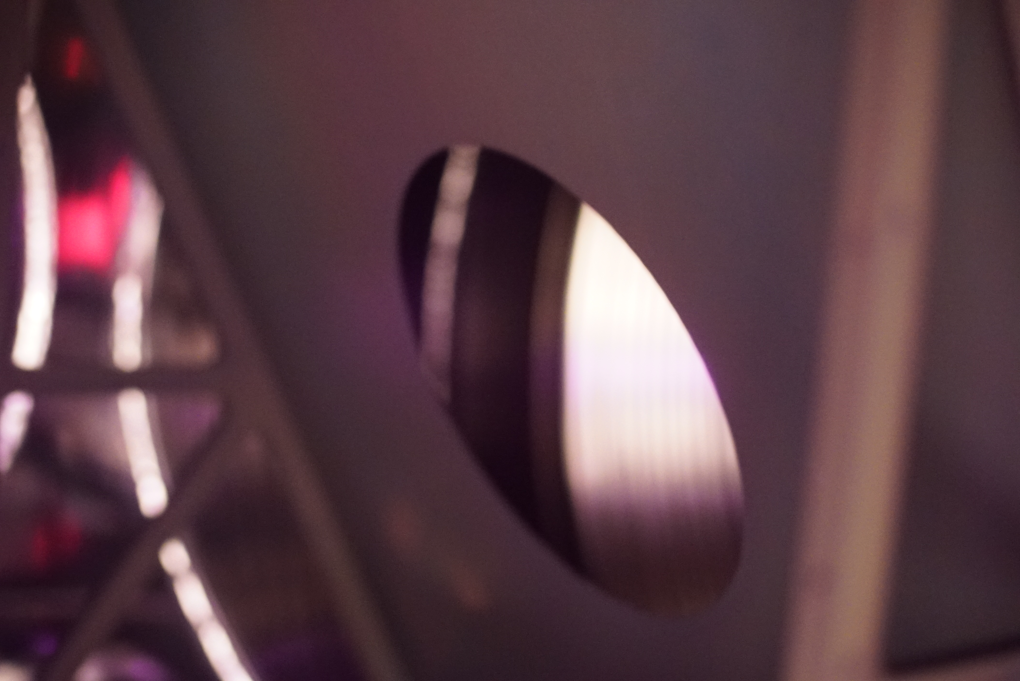
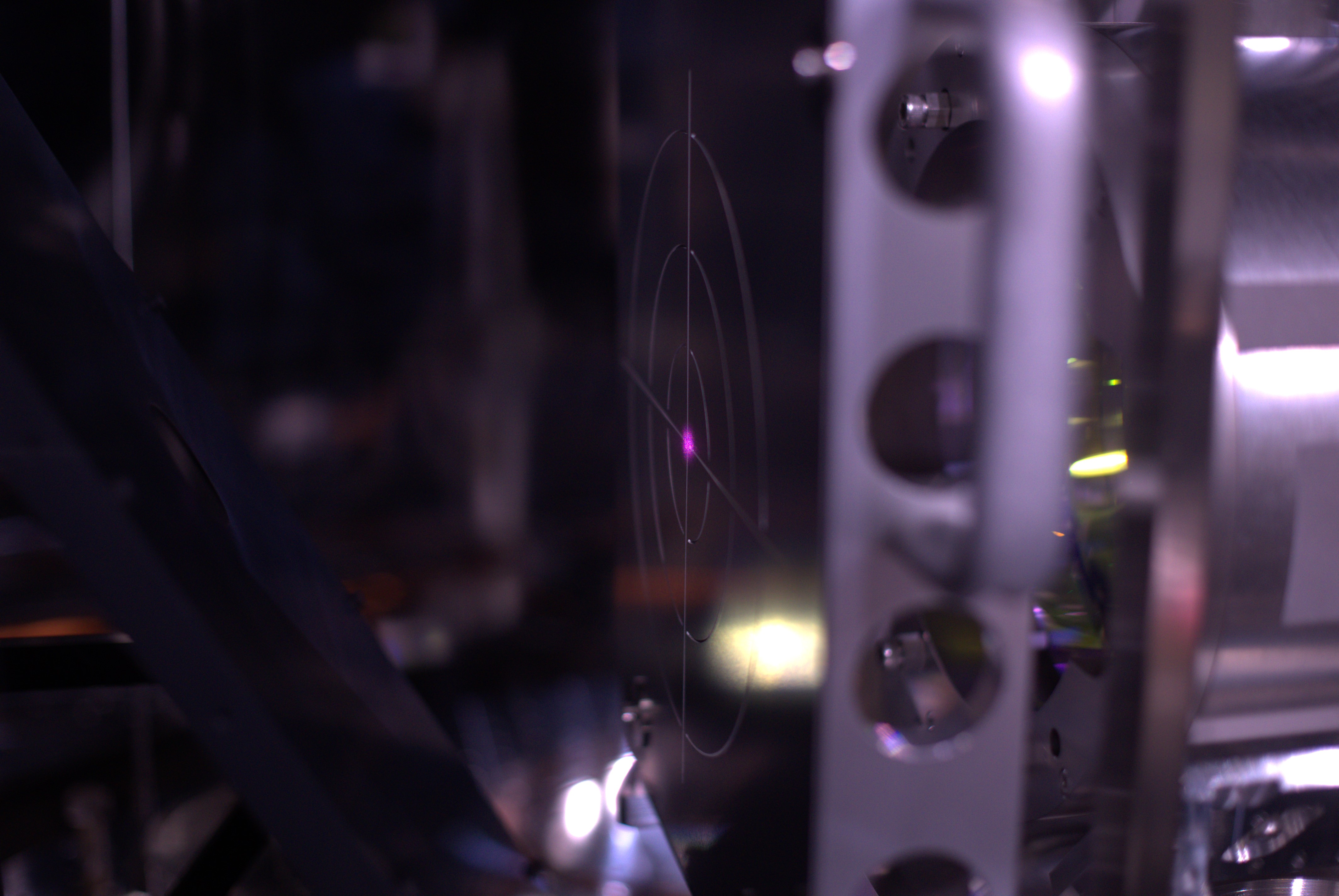
Then, we aligned SR3 so that GRY beam hit the center of ETMY (fig1).
To achieve this condition, SR3 set point was changed as follows:
SR3 pitch: 0 (old) -> 17 (new)
SR3 yaw: -100 (old) -> -90.5 (new)

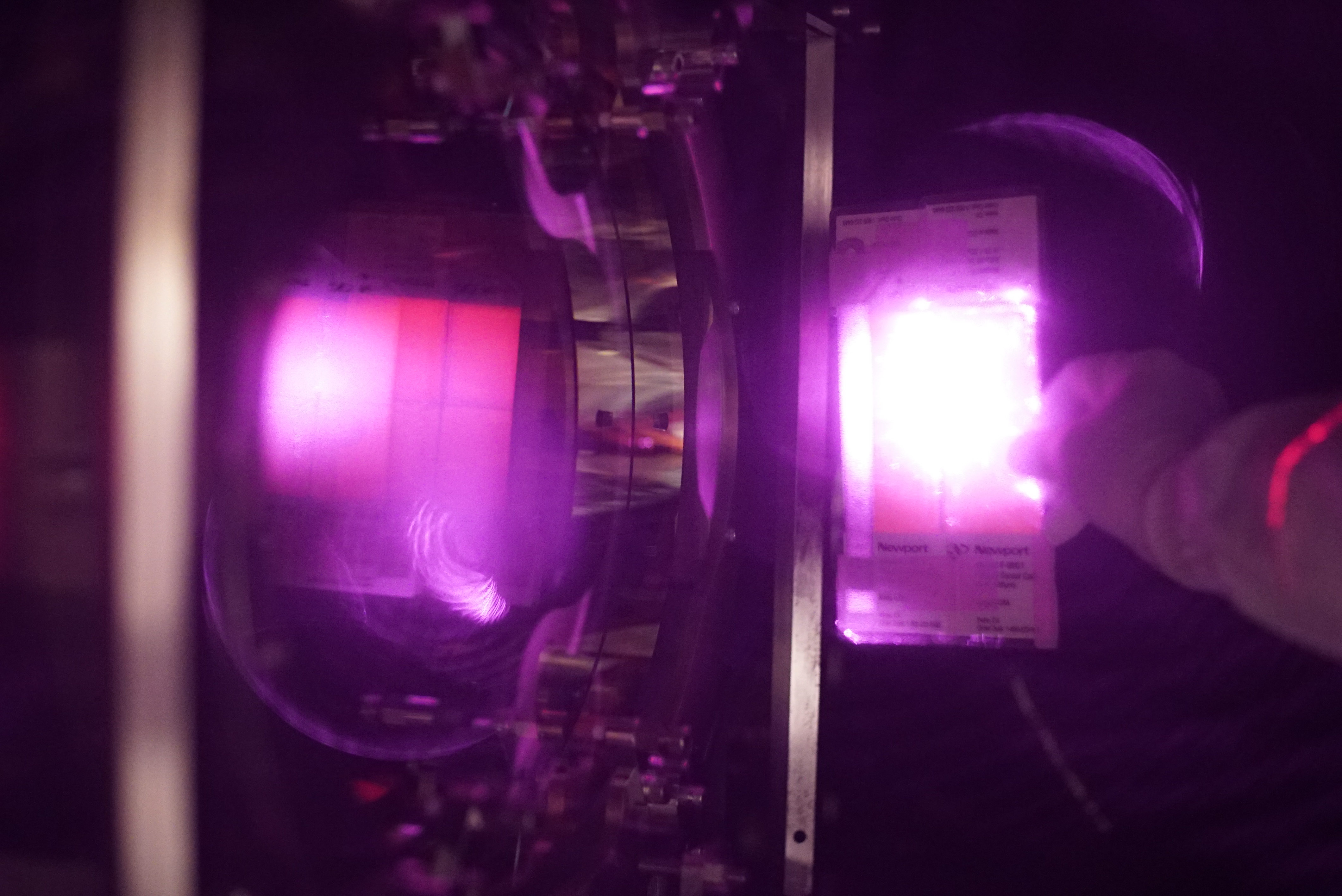
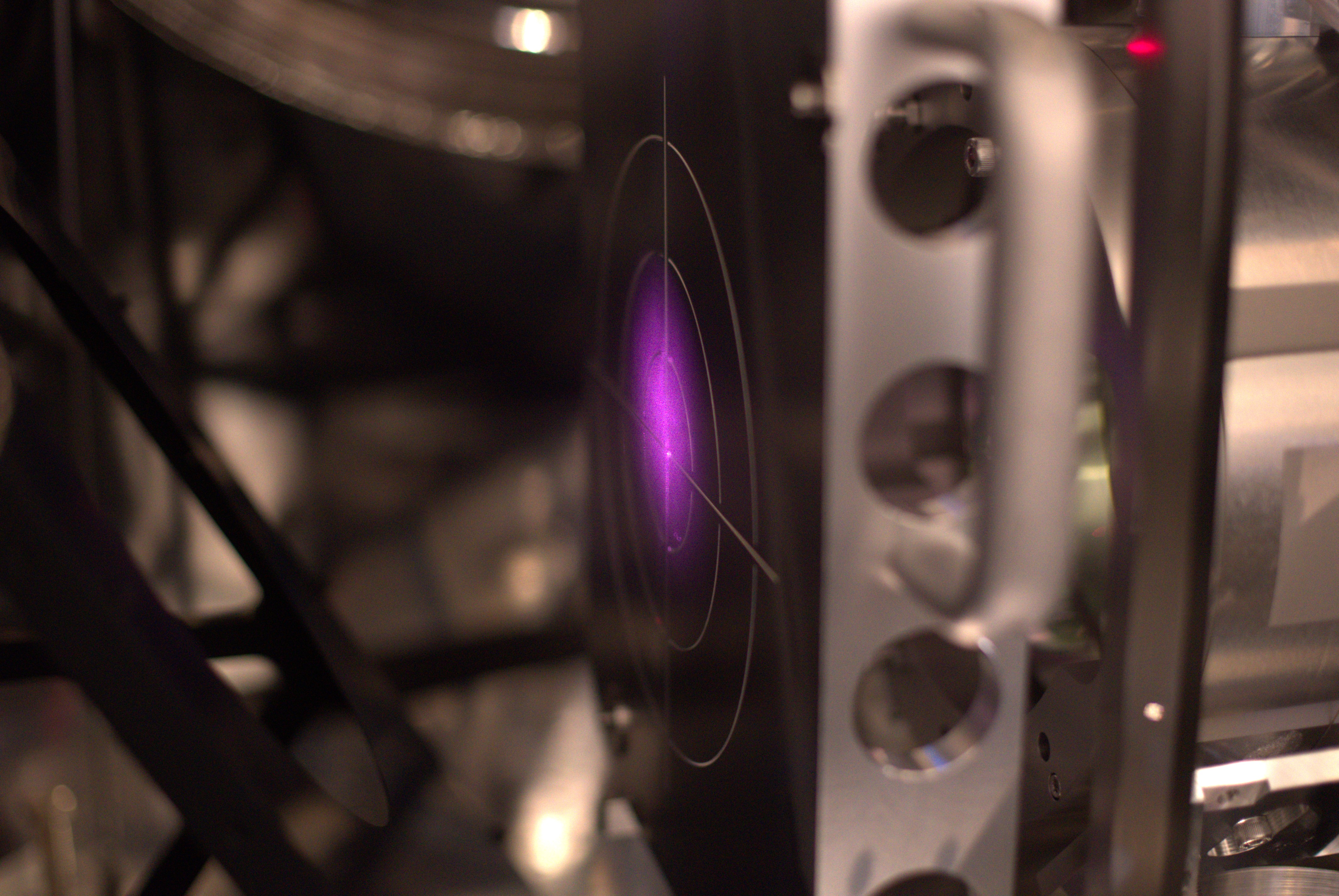
After SR3 alignment, IRMY was tweeked so that GRY reflection hit on the center of GRY REFL PD (fig2 and 3).
As a result, ITMY setpoint was changed as follows:
ITMY pitch: 25.9 (old) -> -11 (new)
ITMY yaw: -16.2 (old) -> -52 (new)

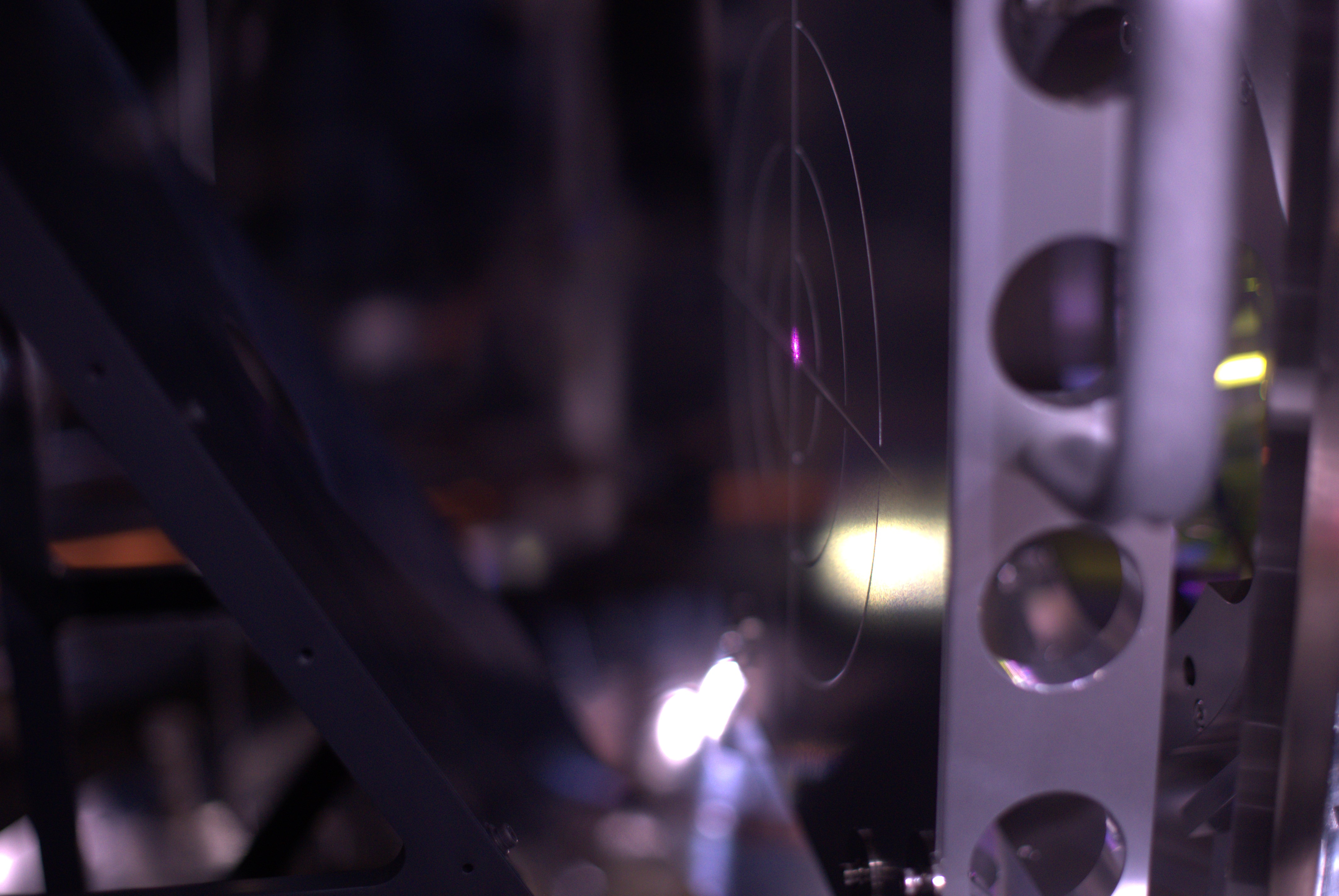
Then, we tweeked BS alignment so that IR reflection at ITMY hit the center of REFL PD (fig4 and 5).
Followings are the change of BS setpoint:
BS pitch: 18 (old) -> -20.5 (new)
BS yaw: -13.9 (old) -> 18 (new)

Then, to find the good alignment of BS by using TMSY GR PD, we first checked the current GRY beam position on TMSY when GRY hit on ETMY center.
However, Yokozawa-san found that GRY beam is not on even the first in-air mirror (upper mirror of the periscope) (fig6).
So, we gave up using TMSY PD to find the good alignment of BS.

Instead of using TMSY GR PD, we set an additional PD in the EYA chamber and connected it to NAB PD channel temporary (K1:NAB-EYA_BAFFLEPD_A).
PD is set so that GRY beam, which is aligned to ETMY center, hits on it.
Then, we closed GRY and found that IR beam can be observed on the PD signals without any additional BS adjustment!!
After that, I slightly move BS to maximize the PD output, and the setpoint became as follows:
BS pitch: -20.5 (old) -> -10.5 (new)
BS yaw: 18 (old) -> 20 (new)

Figure 7 shows the PD output, BS OpLev signals, and IMC trans power.
As you can see, PD power goes to zero when IMC lost lock: so we could confirm that the main IR beam hit on the PD.
So, BS is well aligned with respect to Y arm now.

Note:

With the same alignment, GRX also hit on the PD at Y end (fig8).
So, overlap of GRX and IRX at BS should be also fine.

Images attached to this report
Comments to this report:
takaaki.yokozawa - 6:53 Tuesday 14 May 2024 (29486) Print this report
Fig.1. showed the GRY beam position for periscope at TMSY.
(Sorry I forgot to check the GRY beam inside the TMSY chamber)

Fig.2. showed the PDA which was placed at the EYA chamber
Images attached to this comment
VIS (IX)
takafumi.ushiba - 18:47 Monday 13 May 2024 (29475) Print this report
ITMX trip due to the glitch on MN V1 photosensor

ITMX went to PAY_TRIPPED state around 11:42 today due to glitches on ITMX.
To investigate the glitch source, I kept ITMX in PAY_FLOAT state but it was again tripped around 11:55 today.
The trigger of the trip is large glitch on MN V1 photosensor (fig1).
Since there was almost no effect on the other sensors, it is very likely that the sensor trouble.

Figure 2 shows the MN V1 photosensor signal from about one month ago.
T cursor shows the time when vacuum pumping was started according to klog29307.

The timing when signals went zero is DGS maintainance, so the first glitch seemed to be occured on May 2nd and somehow the glitch rate was drasticaly increased in this morning.
I also checked the signals on IOP model and confirmed the signal shape in payload model and IOP model is almost same (fig3).
So, it is probably the hardware trouble of ITMX but I haven't confirmed yet if the source is inside the vacuum chamber or not.

Considerable solusions:

I haven't confirmed the trouble happens inside the chamber or outside but  I listed up the considerable solusions here in case it is inside the vacuum.
1. Open vacuum chamber and repair.
2. Change sensing matrix not to use MN V1 photosensor for pitch damping control (we could not decouple pitch and vertical but not so probematic because MNV is very stiff and dominant signal should be pitch motion).
3. Use MN OpLev for pitch control not to use MN V1 photosensor for damping controls (This situation is same as ETMY just before the earthquake, so it should work).

Images attached to this report
Comments to this report:
takafumi.ushiba - 8:40 Tuesday 14 May 2024 (29491) Print this report

Figure 1 shows the one-day trend of ITMX MN V1 photosensor
glitch rate and amplitude become small now, somhow.
Also, DC value is changed about 15 hours ago but I have no idea why.

Images attached to this comment
takafumi.ushiba - 8:41 Wednesday 15 May 2024 (29509) Print this report

I modified the sensing matrix (fig1) not to use MN V1 photosnsor to avoid kickng the suspension during the alignment work.
No oscillation canbe observed at this moment.

Images attached to this comment
VIS (PRM)
takafumi.ushiba - 10:24 Monday 13 May 2024 (29473) Print this report
PRM was tripped due to the sudden signal disappearance

When I tried to ALIGN PRM in this morning, PRM goes to TRIPPED state due to the watchdog of BF GAS filter.
Figure 1 shows the GAS signals when PRM was tripped.
After the trouble, I tried to move BF GAS by 1000 cnts manually but no responce (fig2).
Since current LVDT readout is almost zero but IM OSEM is still in range, it is not likely real suspension motion but sensor trouble.
We need to investigate the reason and fix it.

Images attached to this report
Comments to this report:
takafumi.ushiba - 10:14 Tuesday 14 May 2024 (29492) Print this report

To avoid saturation of GAS feedback, I turned off the INPUT of BF GAS DAMP filter of PRM.
After the recovery, we need to turn on it again.

satoru.ikeda - 17:46 Tuesday 14 May 2024 (29502) Print this report

Ushiba-san, Ikeda

Overview
The PRM BF LVDT signal has been lost.
Therefore, the first step is to measure the resistance of the LVDT.

Investigation

1. investigation of resistance values
From Dopbox Paper, the BF GAS LVDT is connected to a flange with Port number: 3-7.

PinResistance[Ω]Inductance[mH]
1-692.210.479
2-7202.740.101
3-8121.268.14

=> No abnormalities; no significant changes compared to the start of O4a.
After measuring resistance values etc., the DSUB cable was reconnected and the signal was restored, although it is not known why.

2. investigation of DSub9P connector
When touching the root of the DSub on the flange side of the cable connecting the flange to the Rack (or more precisely, the side connecting the cable to the conversion cable), a change in signal was observed Fig-1

Countermeasures

The Dsub cable was replaced.
After confirming the effect, the old cable was removed.
The removed cable was handed over to the AEL team for confirmation and repair.

Verification
The value did not change when the cable was touched.
The Guardian confirmed that the cable would proceed to ALIGNED.
The signal difference before and after the replacement was -0.991501 in the value of K1:VIS-PRM_BF_LVDTINF_GAS_OUT_DQ Fig-2
 

Images attached to this comment
Non-image files attached to this comment
takafumi.ushiba - 8:58 Wednesday 15 May 2024 (29511) Print this report

I turned on BF GAS INPUT after the recovery work.

VIS (EX)
takafumi.ushiba - 18:05 Saturday 11 May 2024 (29470) Print this report
Comment to ETMX was tripped (29469)

I checked what happens in ETMX and it seems that F3 GAS watchdog hit the threshould during the health check measurement.
When suspension was tripped, F3 GAs control was turned off and F3 GAS excitation was ongoing for health check (fig1).
Since I have no idea why the template doesn't work well now (I don't change template, so it should work, though...), I will check it in next week.

Images attached to this comment
VIS (General)
takafumi.ushiba - 13:51 Friday 10 May 2024 (29455) Print this report
Comment to Scripts for the suspension health check (28271)

Since Takahashi-san reported health check script didn't work well on Wednesday, I tested it with SR3.
Though I don't change anything, the script seems working well and measurements are started.
Since there were some troubles in DGS on Wednesday (klog29433), it might be due to not the bug of the scripts but DGS troubles.
If Takahashi-san provides us what time he started the script, it might be helpful to investigate further.

VIS (IY)
takafumi.ushiba - 18:10 Thursday 09 May 2024 (29450) Print this report
Comment to Tower part health check (29442)

I checked ITMY and found that almost all GAS filters were low by seravera hundreds of um.
Figure 1 shows the time series of GAS motion when I requested ISOLATED state.
When moving F1 and F2 up, F0 and BF go down once: this implies that suspension is touching at payload.
So, it is very likely that the payload is now sit on the installation flame (or EQ stops) if there is no control.

Figure 2 shows the TF of BFY when ITMY is in TWR_FLOAT state, which keep the suspension height close to the nominal position.
As you can see, resonant frequency is around 30 mHz ad TF seems healthy, so the problem seems GAS filter position.

Since it is not good situation that the suspension is sitting on the installation flame, I kept ITMY in TWR_FLOAT state to avoid it.
So, please keep current guardian state until GAS offload will be performed.

Images attached to this comment
MIF (General)
takafumi.ushiba - 17:26 Thursday 09 May 2024 (29448) Print this report
Alignment check after vacuum closure

[Hirata, Ushiba]

Abstract:

We checked the input alignment and confirmed it seemed healthy.
After that, we centered POP FORWARD QPDs and closed GV between PRM and PR3.

Detail:

First, we aligned XARM with almost the same procedure written in klog29346 (since GRX lock is somehow not so stable, PR3 is manually aligned instead of GRX ADS).
Then, we checked the beam spot in front of PR2 (fig1: IR, fig2:GR): looks good.

After that, we centered POP forward QPDs (fig3).
Then, we closed GV between PRM nd PR3 and checked POP FORWARD QPDs again (fig4).
Only QPD2 pitch value was changed from 0.
Since amount of the change is not so large and final condition should be the same as before closing the GV, we didn't move QPDs after GV close.

Images attached to this report
FCL (Air)
takafumi.ushiba - 14:21 Wednesday 08 May 2024 (29421) Print this report
Air leakage of the clean booth air at the connection port in EYV.

During the EY photosensor work, we found there is leakage of the air for clean booth at the connection port.
Attachment is a movie around the leakage point.

Non-image files attached to this report
Comments to this report:
shinji.miyoki - 15:06 Wednesday 08 May 2024 (29422) Print this report

Please Kimura-san ask somebody to fix it.

CRY (Cryo-payload EY)
takafumi.ushiba - 13:56 Wednesday 08 May 2024 (29419) Print this report
Comment to ETMY photosensor recovery (28811)

[Tamaki, Ushiba]

We measured resistance, forward voltage, and inductance of the newly installed photosensor/actuator cables from the feedthrough flange at EYV.
All measured values are consistent with those during health check before O4a and seem fine.
Following table shows the summary of the measurement (with the values before O4a).

  Forward Voltage (1-6) Resistance (2-7) Inductance (2-7) Forward voltage (3-8)

MNH2 (P6-2) before O4a
MNH2 (P6-2) after cable replace

0.482 V
0.481 V
110.4 Ohms
111.0 Ohms
6.92 mH
6.93 mH
0.946 V
0.946 V

MNH3 (P6-3) before O4a
MNH3 (P6-3) after cable replace

0.496 V
0.495 V
110.0 Ohms
110.0 Ohms
6.93 mH
6.93 mH
0.953 V
0.952 V

MNV3 (P6-4) before O4a
MNV3 (P6-4) after cable replace

0.469 V
0.471 V
111.1 Ohms
111.5 Ohms
6.91 mH
6.91 mH
0.948 V
0.947 V

Also, we measured the resistance of all the other connections like 1-2, 1-3, and so on.
All values are OL, so we confirmed there is no unexpected short among the new cables.

IOO (IFI)
takafumi.ushiba - 16:38 Tuesday 07 May 2024 (29410) Print this report
Comment to STM2 cable cut (29407)

Attached picture shows the current situation inside the IFI chamber.
STM2 pico cables are cut just below the heat-shurink tubes and tied at the STM2 pole with peek tie (red circle in the picture: sorry but cables themselves cannot be seen because they are on the behind of STM2 pole.).
STM1 pico cables are fixed on the optical table with aluminum clamp by M6 screw with vent hole (yellow circle in the picture).

Images attached to this comment
CRY (Cryo-payload EY)
takafumi.ushiba - 8:45 Thursday 02 May 2024 (29375) Print this report
Comment to ETMY photosensor recovery (28811)

We connected the new cables to the photosensors and confirmed that the sensor is working.
Also, we checked the signals while touching the cables around BF but there seems no glitch.
So, new cables seems working well.

We will tie up the cables and fix them onto the payload.

CRY (Cryo-payload EY)
takafumi.ushiba - 18:41 Tuesday 30 April 2024 (29360) Print this report
Comment to ETMY photosensor recovery (28811)

[Dan, Hirata, rTakahashi, Tamaki, Ushiba]

We installed three additional cables between BF and PF (B49, B50, and B51).
Then, we replaced Dsub connectors on BF.
Followings are the cable numbers before and after replacement,

Sensor name cable number before replacement cable number after replacement
H2 (CRYO10) B44 B49
H3 (CRYO11) B45 B50
V3 (CRYO12) B46 B51

Old cables are cut and clamped on the BF.
We will continue the cabling at PF stage tomorrow.

Note:

During the work, we removed radiation shield plates between BF and PF.
They are stored in the cryostt, and need to be reinstalled after finishing the cabling.

VIS (EX)
takafumi.ushiba - 9:55 Tuesday 30 April 2024 (29356) Print this report
Comment to ETMX PAY was tripped (29351)

I checked the reason why ETMX was oscillated.
Figure 1 and 2 show the signals of NB filters and MN DAMP filters, respectively.

DOF5 and MN_DAMP_L was oscillated at 5.1 Hz, which should be damped by DOF5.
So, it is very likely that the reason of the oscillation is DOF5 NB filter.
This filter was optimized when ETMX is at 90 K, so it is neccesary to optimize it again at the current temperature.

Images attached to this comment
VIS (PRM)
takafumi.ushiba - 16:33 Saturday 27 April 2024 (29348) Print this report
Comment to Health check of PRM (28522)

I checked all TFs of PRM.
All TF seem fine though resonant frequency of GAS filter is shifted slightly.

Following is an additional note, which is not problematic.
1. BF coil DoF measurement have a larger gain than before because of the calibration factor update (klog21311 and klog21315).

Images attached to this comment
VIS (PRM)
takafumi.ushiba - 16:26 Saturday 27 April 2024 (29349) Print this report
Check of PRM sensor spectra

I measured the spectra of PRM LVDTs and OSEMs (fig1, fig2)
All seem fine.

Images attached to this report
IOO (IMC)
takafumi.ushiba - 14:37 Saturday 27 April 2024 (29347) Print this report
Reduce IMC-MCL_SERVO filter gain

IMC LSC was often failed when holding the output of MCL feedback.
Since MCE actuator efficincy increased by a factor of 3 due to thechange of the magnet size, I added a gain of 0.3 at FM9 (gain) of IMC-MCL_SERVO filter bank.

Search Help
×

Warning

×